|
MODBUS laajempi esimerkki
|
|
MODBUS laajempi esimerkki
|
Go to the source code of this file.
Macros | |
| #define | F_CPU 8000000 |
| #define | INDICATION_PORT_DDR DDRB /** \def INDICATION_PORT port where all indication leds are connected */ |
| #define | INDICATION_PORT PORTB /** \def INDICATION_PORT port where all indication leds are connected */ |
| #define | ISF_LED 0 |
| #define | COM_ERR_LED 1 |
| #define | RESET_LED 3 |
| #define | RS_LED 2 |
| #define | CONFIGURATION_PORT_DDR DDRC |
| #define | CONFIGURATION_PORT PORTC |
| #define | DEBUG_BUTTON 0x04 |
| #define | CLEAR_BUTTON 0x04 /*!< Location of Clear button */ /* Possible to use the same */ |
| #define | ADDRESS_SELECT_PORT_DDR DDRC |
| #define | ADDRESS_SELECT_PORT PINC |
| #define | ADDRESS_SELECT_PIN 4 |
| #define | ADDRESS_SELECT_BIT_MASK 0x0F /** 4 bits for address reading from Hardware*/ |
| #define | NRO_OF_SENSORS 4 |
| #define | SENSOR_PORT_DDR DDRA |
| #define | SENSOR_PORT PORTA |
| #define | SENSOR_PORT_IN PINA |
| #define | SENSOR1 0x01 |
| #define | SENSOR2 0x02 |
| #define | SENSOR3 0x03 |
| #define | SENSOR4 0x04 |
| #define | SENSOR_CLK 0x00 /* Changed on 21.1.2010 (Previous value 0x06) */ |
| #define | RESET_LED_ON INDICATION_PORT |= (1 << RESET_LED) |
| #define | RESET_LED_OFF INDICATION_PORT &= ~(1 << RESET_LED) |
| #define | ISF_OFF INDICATION_PORT |= (1<<ISF_LED) |
| #define | ISF_ON INDICATION_PORT &= ~(1<<ISF_LED) |
| #define | ENABLE_SENSOR_MEASUREMENT TIMSK |= (1<<TOIE0) |
| #define | DISENABLE_SENSOR_MEASUREMENT TIMSK &= ~(1<<TOIE0) |
| #define | IF_CLEAR_BUTTON_IS_ON (CONFIGURATION_PORT | (1<<CLEAR_BUTTON))==CLEAR_BUTTON |
| #define | IF_DEBUG_BUTTON_IS_ON (CONFIGURATION_PORT | (1<<DEBUG_BUTTON))==DEBUG_BUTTON |
| #define | RS_LED_OFF INDICATION_PORT |= (1 << RS_LED) |
| #define | RS_LED_ON INDICATION_PORT &= ~(1 << RS_LED) |
Functions | |
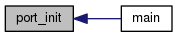
| void | port_init (void) |
| Initializes all needed ports. More... | |
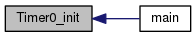
| void | Timer0_init (void) |
| Initializes Timer/Counter overflow Interrupt. More... | |
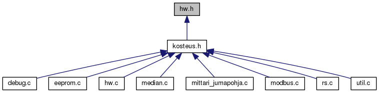
Header file for hw.c.
Date
Versions:
$Log$
| #define ADDRESS_SELECT_BIT_MASK 0x0F /** 4 bits for address reading from Hardware*/ |
| #define ADDRESS_SELECT_PIN 4 |
| #define ADDRESS_SELECT_PORT PINC |
| #define ADDRESS_SELECT_PORT_DDR DDRC |
| #define CLEAR_BUTTON 0x04 /*!< Location of Clear button */ /* Possible to use the same */ |
| #define COM_ERR_LED 1 |
Communication erroro LED
| #define CONFIGURATION_PORT PORTC |
| #define CONFIGURATION_PORT_DDR DDRC |
| #define DEBUG_BUTTON 0x04 |
Location of DEBUG switch
| #define DISENABLE_SENSOR_MEASUREMENT TIMSK &= ~(1<<TOIE0) |
| #define ENABLE_SENSOR_MEASUREMENT TIMSK |= (1<<TOIE0) |
| #define F_CPU 8000000 |
| #define IF_CLEAR_BUTTON_IS_ON (CONFIGURATION_PORT | (1<<CLEAR_BUTTON))==CLEAR_BUTTON |
| #define IF_DEBUG_BUTTON_IS_ON (CONFIGURATION_PORT | (1<<DEBUG_BUTTON))==DEBUG_BUTTON |
| #define INDICATION_PORT PORTB /** \def INDICATION_PORT port where all indication leds are connected */ |
| #define INDICATION_PORT_DDR DDRB /** \def INDICATION_PORT port where all indication leds are connected */ |
Indication LED parameters
| #define ISF_LED 0 |
pin where ISR LED is connected in INDICATION_PORT
| #define ISF_OFF INDICATION_PORT |= (1<<ISF_LED) |
| #define ISF_ON INDICATION_PORT &= ~(1<<ISF_LED) |
| #define NRO_OF_SENSORS 4 |
| #define RESET_LED 3 |
Reset LED
| #define RESET_LED_OFF INDICATION_PORT &= ~(1 << RESET_LED) |
| #define RESET_LED_ON INDICATION_PORT |= (1 << RESET_LED) |
| #define RS_LED 2 |
| #define RS_LED_OFF INDICATION_PORT |= (1 << RS_LED) |
| #define RS_LED_ON INDICATION_PORT &= ~(1 << RS_LED) |
| #define SENSOR1 0x01 |
| #define SENSOR2 0x02 |
| #define SENSOR3 0x03 |
| #define SENSOR4 0x04 |
| #define SENSOR_CLK 0x00 /* Changed on 21.1.2010 (Previous value 0x06) */ |
| #define SENSOR_PORT PORTA |
| #define SENSOR_PORT_DDR DDRA |
| #define SENSOR_PORT_IN PINA |
| void port_init | ( | void | ) |
Initializes all needed ports.
| void Timer0_init | ( | void | ) |
Initializes Timer/Counter overflow Interrupt.
 1.8.11
