|
|
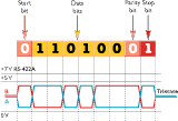
| V.11/RS-422 is
a standard interface which is suitable for industrial applications. It was
created for the construction of multidrop data buses, between a main
computer and a number of terminals. The interface is balanced, uses a
4-wire format and is relatively immune to interference. The interface
changes the polarity of the wire pair depending on whether a 1 or a 0 is
to be transmitted. RS-422 was originally designed to handle 10 units and can now be set up with up to 32 units connected. The maximum recommended distance is 1 200 m (100 kbit/s) or 50 m (10 Mbit/s). RS-422 can be integrated with RS-485, RS-423-A and RS-449 via converters. | |
 |
It is designed for data
buses with up to 32 units and is suitable for multidrop networks with
master/slaves. It is recommended for distances of up to 1 200
m. The great advantage of using this interface is that it can reverse the direction of communication which allows for halfduplex transmission on 2-wire lines. RS-485 is the transmission method underlying many popular fieldbus standards for instance, Profibus, Bitbus and Interbus-S. |
| RS-485 can be used with 2-wire in various master/slave systems, where every slave is addressable. In a 2-wire solution the data direction must be controlled. This can be achieved with a handshaking signal (RTS/DTR) or by means of the data flow. Connected units must be capable of what is termed tri-state, i.e. a listener mode, in which the inactive transmitter enters a high-impedance state thus not loading the line. | |
 |
It is recommended to terminate the line with a
circuit of equal impedance to the characteristic impedance of the line.
For RS-422 and RS-485 a 120 ohm resistance is recommended. The termination
should be placed as shown on picture
RS-485. The purpose of the termination is to prevent the reflection of data at the ends of the cable. If there is no active driver on the network the line can be forced into a known idle state with a fail-safe circuit. Without this circuit it is likely that the line will pick up noise and falsely trigger the receivers leading to problematic communications. |
| When using an RS-232 to RS-422/485 converter
it is important to remember that an RS-485 driver sometimes has to enter
tri-state or become a receiver. Normally the RTS signal from the RS-232 circuit is used to control the state of the converter. To work correctly the RTS signal from the RS-232 device must go high for the duration that data is being transmitted from it and go low to allow the converter to receive any message back. If this signal is not available then it is necessary to use converters that can control the data direction from received data alone. | |
| ´ If a twisted wire pair is used, it should be
terminated with a 120-ohm resistor. ´ The RS-232 cable should not be longer than 15 metres and keep the RS-422/485 stubs as short as possible. ´ RS-422/485 guarantees transmission distances up to 1 200 m for data rates up to 100 kbit/s. Longer distances can be allowed at lower speeds. | |
| RS-485 |
 |
| We mentioned earlier that V.24 does not recommend the use of cables longer than 15 metres. Consequently, short-haul modems are used for longer connections. Short-haul modems are sometimes called line-drivers or base-band modems. These modems transform the V.24 interface into defined signals which are transmitted over twisted pair or fibre optic cable for distances up to several kilometres. The receiving short-haul modem transforms the signals into V.24 again. The modems must be of the same standard and must share a commonline interface in order to communicate via the cable. | |
| One problem associated with using ordinary
copper wire for long-distance communication is that transmission is
relatively unreliable and the risk of interference is high. The
transmission speed often has to be reduced to maintain reliability. A
tried and tested method of improving reliability which has been in use for
a long time is to transmit an electrical current over the
network. Current loop is the oldest known method. V.24 signals are represeted as a pulse of electrical current or no electrical current in the wire pair. Current loop is sometimes refered to as TTY. To supply each wire pair with current, the transmitter is either connected as active and the receiver as passive, or vice versa. Current Loop results in more reliable communication but is relatively vulnerable to interference since the current loop is not balanced, and there is no accepted standard for Current Loop. A more advanced method is the balanced 10 mA current loop described below. | |
| Westermo has developed its own improved
interface for its short-haul modems. The aim is to improve the reliability
and performance of the modems and reduce their vulnerability to
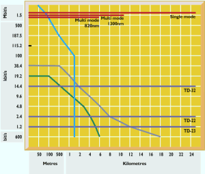
interference. WestermoÝs modems transform the signal to be transmitted into a balanced ▒10 mA current loop. The connected units are always electrically isolated from each other by means of galvanic isolation. The method involves changing the direction of the current in the wire pair depending on whether a high or a low signal is to be transmitted from the V.24 interface. On the transmitter side, there are two amplifiers which drive ▒10 mA into the line and on the receiver side there are two optocouplers which read this signal. Current always flows in the loop, even when no data is being transmitted, with the exception of when you chose to use a hardware handshake line to activate the transmitter and hence provide a way of sending hardware handshake information across a link. This method is very reliable, there is very little risk of interference and data can be transmitted at distances of up to 18 km. | |
|
| |
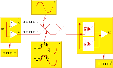
| A balanced current loop is less sensitive to interference than a non balanced system because when noise is applied to the line both wires are effected the same way and hence the differential between the two wires that encodes the data is maintained. See drawing. | |
 | |
| 1. Data in to the
transmitter. 2. Voltages on lines A and B are inverted depending on data hence driving current either one way or the other through the circuit. 3. Common mode interference on the line. 4. Noise superimposes onto data stream. 5. Data is received and decoded unchanged from when it was transmitted (1). |